Latest developments April 2003:
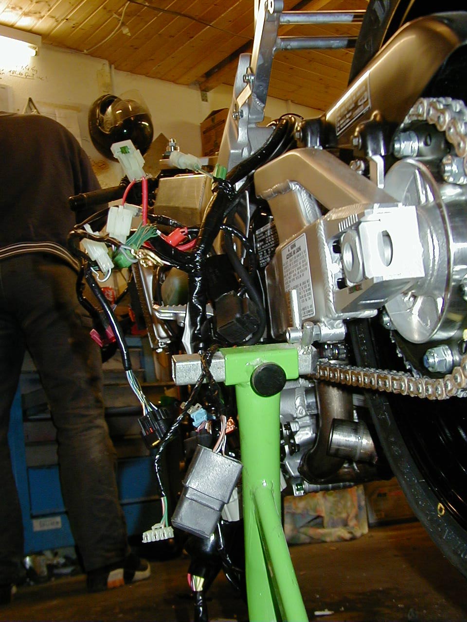
What you see here,that's my Model-Bike,built out of all the crashed Parts of friends : Frame,Swingarm,fork,wheels,crankcase,heads,and so on,always good to have a model for wire harnesses,custom Exhausts,the plastic (fairing) models................
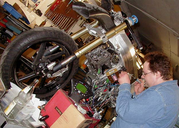
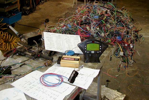
Stephen and me,we began to wire our Bikes with the new Motec ECU System.This was a special assignment I had to do,wiring a MyChron3 with a Motec M4 pro into a std. wire harness......hardest Job I ever had-regarding connecting things.3 Wiring Diagrams I've had to bring into one . But it looks like it works.Very interesting,the Motec system allows you to write your own table even for each sensor,means you don't have to buy special sensors for this System -you just use the one you've on your Bike. I.E. the speed-sensor is a 12V Hall-type,which also works with the 8V reference + which the Motec puts out (and + 5V reference also,which you need for throttle-pos , map and temperature-sensor)
 This is how I start,using all the wire colours from OEM harnesses rebuilts for
this very special wire harness I've mentioned above.
This is how I start,using all the wire colours from OEM harnesses rebuilts for
this very special wire harness I've mentioned above.
So-have done the short road-wire this weekend for side Rads,i went for only
one main fuse,got rid of the bank angle sensor+relays therefore,got rid of the
high-beam relays,that doesnt mean i've got no high beam,it means i've used a
simple 0.5$ I-0-II switch,which you can exchange in 47 seconds for 50 cent
when it's burned after 5 seasons on road.
(well i don't know if you've read it already-the high-beam relays is mounted
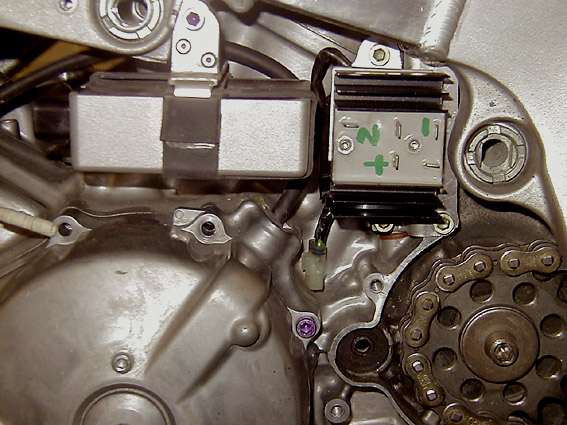
std. at the taillight,we shouldn't rack our brains why).The Bits you've to
relocate: ECU,Converter,Rectifier,2 load-relays,turn signal-relay,ignition
coils.Advantage:if you once go for front rads you can keep the electronics
where they are,they're not concerned by rads-relocation.I think i'll offer the
3 main-brackets(Carbon) for ECU,rectifier and converter soon,so that'll save
you 6-7 hours work.But you still can calculate 30 hours for the wire-mod i've
you havn't done it before.This was my 7th RC51 wiremod and it still took 20
hours,even i could name each wire.Some assorted comments(most of i've already
typed here):
| IMPORTANT: I havn't checked it,these comments work at European Models, probably for US Models also,but-I havn't ckecked it,please compare diagrams. |
1:don't mix up the 2 different Pink/green wires coming from ECU,have a
closer look at the wiring-diagramm.
One leads to the injection manifold-the other one is speed sensor and leads
into dashboard + ECU
(
2.if you want to get rid of the fuse box: the green-white and the green-red
ECU wire you can put together and then on ground (green),that'll allow you to get rid of the
clutch-switch,side
stand-switch!
3:the neutral light green wire you can connect directly with the
instrument-panel lightgreen/red wire.
4 all green-orange wires put together but not on main-ground,these are
seperate (logic) grounds of ECU for sensors
5.use the bank-angle sensor Relays as main relais for Power-supply,this will switch main+ ,means you can choose a brown,brown/black or red wire for main+ then.Pay attention you've got enough mm2 for wire.Think of only the fuelpump and headlights need real electric power .
6.regarding comment1:except the isolated green/orange wires you can put together all green,greeen/black,grey/green and remaining green/purple wires for main-ground.NOT grey /blue
7.If you want to keep your bank angle
sensor,simple:the white/black connect (put on)with the thin black wire coming
out of green plug of starter switch (it's necessary,that the bank anle sensor
electronic is still on + when main power realais has cutted of the power supply
for the other Electronics), the orange/red
with orange/red of relay,the green on ground. The thin black wire of Bank angle
sensor relays is going up to the green plug of Engine-start switch unit:.Coming
back out of the switch is a thin white/black wire-this you have to connect with Battery +.
(Attention,what i'm talking from: NOT the wire-colours from Switch to green
plug, i mean the colours FROM green plug into main wire harness,important
because (don't know why Honda did this) the black/white changes into black and
reverse -before/behind green plug.
8.Don't mix up red/yellow and yellow/red
That's it for now
So,began with the 2nd RC51,from Zero all again,but now i made some Pics for you of the Wire-loom-mods growing,means,where you can start and how (not necessary should..). Bending,sawing ,filing, thats maybe not for everyone,but it's easyer done and faster,if you know,where to start.
To Enumerate each bit,which is to relocate:
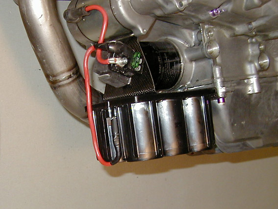
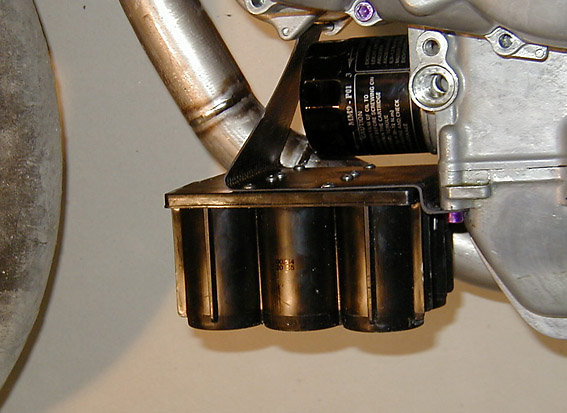
1 .Battery + Starter-relais :i
found out,if i built this Bracket from 6 plys Carbon,it'll be an excellent spot
to fix the lower front Rad too !But you'll find the Pics then here
2. The
CPU 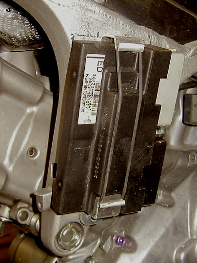
you need a 2nd thread for upper bracket,same shape
3. The Ignition
Box 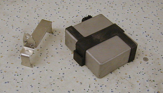
4.Rear Coil (shorten the ignition Cable
then) 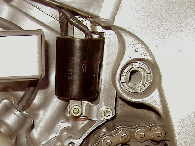
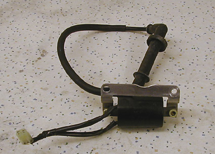
Therefor use the std.front ignition Coil-bracket,tighten it only with one screw-no Problem.
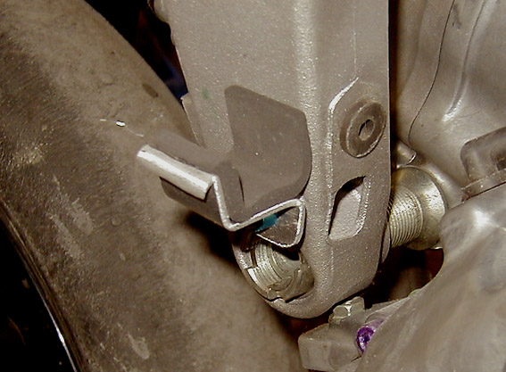
5.Front
Coil
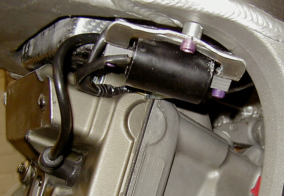
Make a thread into Frame,i've cutted out the rear std.Bracket from Subframe to be faster.
6.....and 4 Relais you've to store,i made a bracket for
all-also a overall- view: 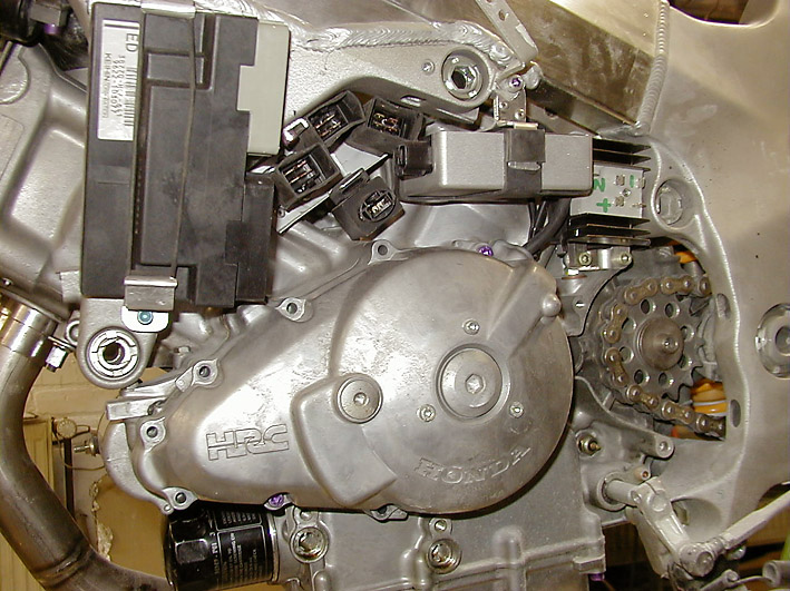
So-i'll provide you with pics of every step from wireloom growing next weeks.-
So far so good.
But now: CLICK FOR PAGE 2 - there it will go on wire by wire
The old Site:
Took about 3 days to mod this Wire,had to
look,where the Ignition,Relais ..... can take place.The objective was :still
keeping the std.didital
Cockpit,but the rest must be a roaduse cutted wire
for lowest possible weight,by
- location of every Item as far as possible in the Centre of Bike
-whole electrical components at one side
-minimum lenght of each wire,so:
- everything had to come together in one area (max .distance -coil to coil 40 cm)
the weight effex: 1.7 kg less weight,not included
secondary effects as battery cable lenght,missing switch ,ignition cable
lenght,minimum of holders,etc.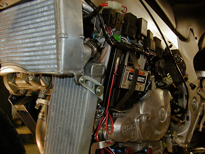
Steering effex :.......
somehow you've to begin: attention download
!!